Tuesday, June 20, 2017

Render Appearance Search Path

The problem with using content downloaded from the internet is that families do not contain any of the textures, aka image files or render appearance images, used in the materials. This becomes evident when you render and see a list of missing render appearance images as shown in the image below.
That textures are also missing is evident by the exclamation mark symbol in the Material dialog. Notice the image preview area, in the image below, is bright red with this attention getting symbol.
Some manufactures, such as Herman Miller, offer a download link for their materials/textures. However, this is really only useful for the materials already defined in the family. With furniture, for example, there are lots of material options. The definition of the material is more than just the texture itself; image scale, cutouts, reflections, etc. To help with this challenge, Herman Miller also offers a Revit Material Library as shown in the image from their website below.

  • I wish more manufacturers would offer Material libraries; some don't even offer the texture files.

The image files can be saved to a common folder on your network. An important step to make sure the materials see the appearance textures, is to specify the path via Options as shown below. This is also important to set, so the materials are found when rendering; Revit does not just search your hand drive and entire network looking for these missing item; and your location is not likely to be the same as the folks from Herman Miller who made the content.
Once the path is set properly, Revit should be able to find the textures. In the image below, notice the texture size and cutout information are part of what define the material... not just the image file itself. Also, some manufactures even fill out the Identity tab information. The Herman Miller Material Library does not appear to add the identity information; which is a missed marketing opportunity.
My book, Interior Design using Autodesk Revit 2018, touches on the use of content and textures from manufactures.

There is a lot more to say on this subject, but that will be for future posts.

Saturday, June 17, 2017

Revit's Section Box Tips and Tricks

Fun fact: I wrote this post in-flight between Minneapolis and Amsterdam, in route to visit my family's past Russian exchange students--and ultimately posted this from St. Petersburg, Russia. I had mentioned this impending trip in a speaker spotlight interview for BILT-NA in Toronto.

There are a number of tips and tricks related to Revit’s Section Box feature. I will share several of them in this post. Please add any additional tips you may have in the comments section below.

A Section Box can be activated in a 3D or Camera view via Properties as shown in the image below.
Once activated, and selected, each of the six sides of the Section Box can be adjusted using the grips. The grips are always centered on each face.
About those grips… they can be hard to find and tricky to select. Knowing they are always in the center helps in locating them. If you click and miss the grip, the Section Box deselects—which is a pain. Notice the grip is composed of two arrows? If you single-click one side, or the other, the Section Box face will adjust a slight amount in the direction selected.

In addition to the six grips, there is also a quick access Rotation icon, see the image above.

For more control in sizing and rotating the Section Box, I like to adjust it in plan, elevation and section views. You can make the Section Box visible by selecting it in the 3D view and then using Ctrl+Tab to step through the open views. This requires the plan or elevation view to already be open. Additionally, the Section Box will become deselected if you step into another project or family.

Another option is to open the plan or elevation view and then right-click on the 3D view in the Project Browser as shown in the image below. Any 3D or Camera view with Section Box checked will show this option.

Once selected, you can drag a side to be more accurately centered on a wall (in plan) or above/below a floor (in elevation).
When the Section Box is selected, in a plan view, use the rotate command. The angled element in the next two images is a good example of when rotating a Section Box can be helpful.
 In this example, the floor cut aligns with the element and the adjacent columns are excluded.
Another great way to leverage the Section Box tool is via the Selection Box command. Select one or more elements, as in the image below, and then click the Selection Box command.
The result is your default 3D view is opened and the Section Box is turned on and adjusted around the selected elements as shown in the next image.
In general, I like to think of this as a “throw-away” Section Box. Seeing as it is applied to the default 3D view, I am guessing that was the developers intent as well. When done with this Section Box, just turn it off. A view does not remember a previous position of an adjusted Section Box… thus, whenever it is toggled back on, it will reset to align with the extents of the model. If you want to save a Section Box adjustment, for future review, or to place on a sheet, simply make a copy of the default 3D view.
 Of course, the Section Box can be adjusted as needed,,,
If the cropped view will be placed on a sheet you may want to turn off the Section Box visibility via Visibility/Graphics Overrides.
As long as the original element(s) is within the Section Box, it is possible to use the Displace Elements command to preposition items outside of the Section Box as shown in the image below.
Finally, the Section Box can be used to save a lot of time when rendering a still image in Revit. I talked about this in the ArchVision webinar... click here to see my post about that and watch the recording.

Wednesday, June 14, 2017

Revit Material: Material Name in a Family

How can we easily share materials between families? There are a few different ways to approach this depending on your needs. One is to create a custom material library, another is to use Transfer Project Standards.

If the Material is already setup in the project environment, it will NOT be changed when loading families with the same materials. Revit assumes the project is correct and will not change that material every time a family is loaded. With that knowledge, all you really have to do is make a dummy material with the correct name, load it into a project with the correct material (i.e. identity, graphics, appearance, etc. settings) and then open that family for editing. Now you have a family with the same settings.

On a related note, one could also use the Revit Family Processor (by CTC Express Tools) to quickly add, delete or change Materials in several families at once. This has some limitations (due to the API as I understand it) but can definitely help. The image below shows how one might add a Material name (LHB Maple in this example) to several families.

  • FYI: The Family Processor is a great way to get rid of all the default Materials loaded in your content (which came from the family templates).


Tuesday, June 13, 2017

Image Defines Transparency in Revit Material

Quick post today... an image file can be used to define a transparency in a render appearance asset as shown in the first image below. This could represent an etched or vinyl pattern on glass.

The lighter areas of the image are more transparent than the darker areas. Click on the image preview to adjust the size of the image (i.e. the pattern on the glass).

The result can be seen in this 3D view from a healthcare project...

Monday, June 12, 2017

Creating a Fence Material and Finding Local Assets

When you need a new material, searching the project and Autodesk libraries is the best place to start (see image below). Sometimes a material does not exist, as in this “fence” example, but an Appearance Asset does; which will get you part of the way there.
Searching for a material
Searching the Asset library reveals a chain-link fence option.
Searching for an asset
When this asset is loaded into a Material, it contains several settings, such as image size, cutout and Bump.
Adding a cutout image for a chain-link fence material
The image below shows the images used to create a fence render appearance (visible in realistic and rendered views). For these images, I did a Google “Images” search and quickly found a tillable image of a fence. Then I made a copy of the image, edited it in Photoshop to look like the second image below (which took about one minute), and then assigned this image as the “cutout” on the Appearance tab. The black areas in the cutout image are the transparent portions as seen in the rendered image on the right.
Combining main image and coutout image to produce result shown on right
For the fence example, you would still need to manually add the Identify and Graphics information manually. For example, the surface pattern and Texture Alignment (to make the drafting views and rendered views align).

Another cutout example...
Back rest mesh material: cutout: Furnishings.Fabrics.Netting.Mask.jpg

Surface pattern texture alignment
Another thing you can do is search the materials and textures folders on the hard drive. The image below shows the results from searching for “fencing” at this location (in Windows Explorer): C:\Program Files (x86)\Common Files\Autodesk Shared\Materials

As you can see there are several “fence” options not revealed in our previous searches (discussed above).
Searching the materials folder via windows explorer
  • TIP: Switch to thumbnail preview mode to see the images.
You can even search in the Revit dialog’s as shown below.
Searching within the Revit open/load dialog


Sunday, June 11, 2017

The Free Tools in CTC BIM Batch Suite

Last week I used a few CTC Express Tools to save a ton of time and thought I would share that process here. What's better, two of the three tools I will discuss are free!

I needed to get a few hundred families out of a large project, add, change and delete some parameters (plus add formulas and a lookup table) and then load them back in. Per the image below, it is possible to simply export all the families from a Revit project, but for a large project with hundreds, if not thousands, of families, that would take a long time.

Enter CTC BIM Batch Suite for a more surgical way in which to harvest content from a Revit project.

  • FYI: When installing this Revit add-in, you have the option to install a free PDF writer as seen in the iamge below. This shows up in all programs, such as Microsoft Word.


The add-in has two free tools; Family Exporter and Family Loader. These are the two I will be talking about. The other two commands require a license.


The Family Exporter allows you to select which categories to export. Plus you can search, add prefix/suffix and more as shown below. I just needed the electrical content, so that is all I selected.


Notice, we can also segregate the exported content into sub-folders.


Several of the CTC tools provide a "results" dialog as shown below. The trick is to look for anything red on the right... that means something did not work.


All the content is now available via Windows Explorer!


Now, I needed to add, delete and modify parameters in all of the exported content. I used the Family Processor from the CTC BIM Manager Suite. This tool is not free, but it can be purchases as a network licenses and shared within a firm. I also replaced a lookup table and added formulas as seen in the image below.
  • FYI: these settings can be saved to a file... in fact, these settings were prepared by Blake Guither, from the MEP firm Gausman & Moore, who I am working with on this project.


Finally, to get the content back into Revit, I used the free Family Loader tool. Notice the "Suppress overwrite dialog" check box? Huge time saver!

  • FYI: I wish this tool had a "use current project" option. You have to browse for the host project to load content into... this is tricky when the project is in C4R; the local file is in a obscure location.


Good stuff!


Saturday, June 10, 2017

Revit Fill Patterns - Part 2

In my previous post on Fill Patterns, I mentioned the Revit Idea about "Double Patterns" being accepted bu Autodesk. Pieter Schiettecatte commented on that post about being surprised Revit could not do this when he first started using Revit. His comment inspired this post (thanks Peter!).

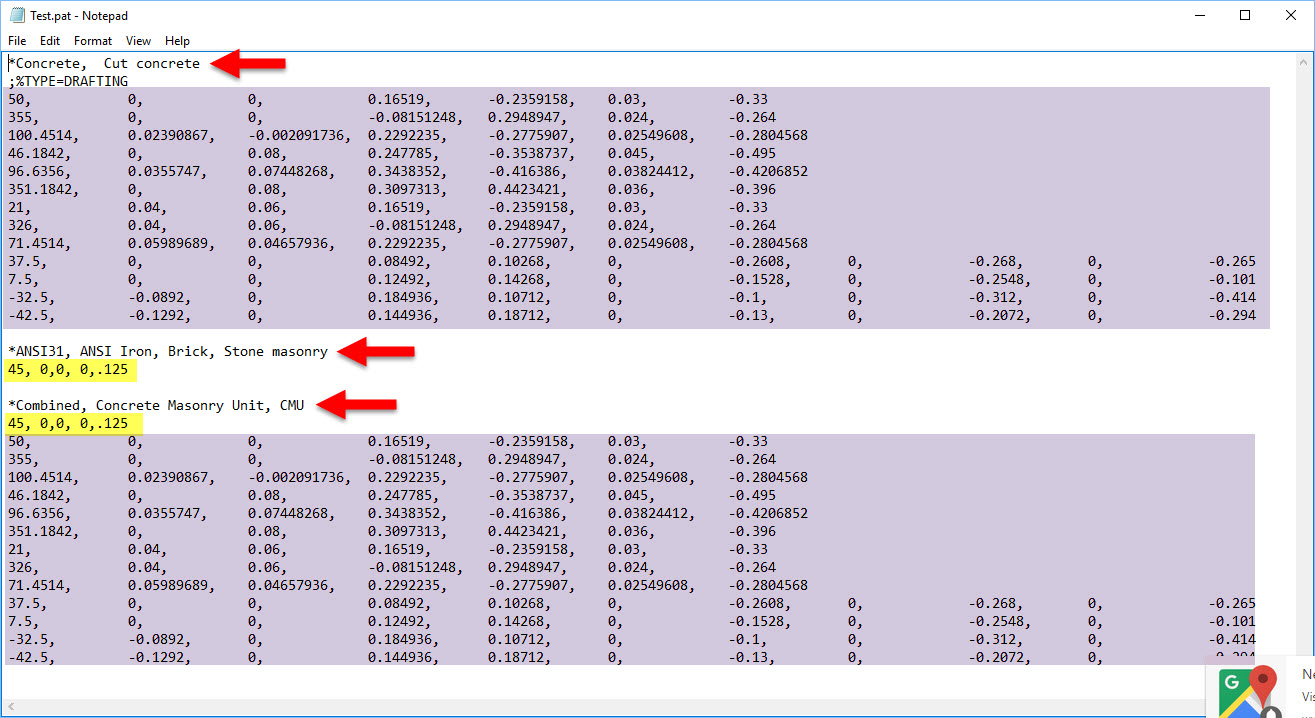
Although we cannot currently use two patterns at the moment, this is a trick to doing it when really needed. Simply combine the two patterns in the text file, creating a new pattern!

Notice, in the sample text file (Test.pat) below I copied the "Concrete" pattern from the Revit.Pat file (comes with Revit) and the "ANSI31" pattern from the Acad.Pat (comes with AutoCAD). I then created a new pattern by simply combining those two patterns to make a third option.


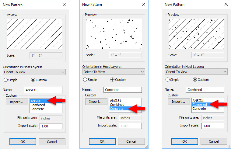
Here is the result in Revit for the sample pattern file and the three options...


To use the custom file in Revit, I clicked the Import button shown in the dialog above and browsed to the test file. There are lots of PAT files for AutoCAD (and Revit, they are just often called Acad patterns online) available via a web search.
  • Revit's Revit.pat file is located here: C:\Program Files\Autodesk\Revit 2018\Data
  • AutoCAD's Acad.pat file is located here: C:\Users\User\AppData\Roaming\Autodesk\AutoCAD 201?\R22.0\enu\Support
One more quick note about the dialog above, when a custom pattern is imported the scale can be set via Import Scale. This is a one-time opportunity, and if you get it wrong you have to delete the pattern and recreate it.

The Import Scale option can be used to create a new pattern without the need to edit the text file. For example, the Revit.pat file comes with a Block 8x8 pattern. If you need a 6.25" x 6.25" running bond tile pattern, just import the block pattern at the scale factor of 0.78125.


It would be nice if the Import Scale option offered and X and Y scale, rather than a just proportional. That would allow almost any tile size to be created quickly. Even better, a built-in feature to graphically edit and create fill patterns within Revit would be wonderful! I am not a big fan of editing text and xml files.

Friday, June 9, 2017

Logitech Unifying Receiver

Here is a nice tool from Logitech which allows you to pair various Logitect input devices with different Logitect USB receivers! So, the same USB receiver for your wireless mouse at your desk can work with the wireless mouse you keep in your backback or laptop bag!

http://support.logitech.com/en_us/software/unifying


Thursday, June 8, 2017

International Books Sales

When I speak at Revit/BIM conferences I always giveaway a few of my textbooks. And, for the ArchVision webinar earlier this week, SDC Publications offered to provide 5 books and cover the shipping costs!

For the RTC, now BILT, conference in Europe, Singapore and Australia I had several people who did not win a book ask how to buy a copy. Until recently, it wasn't really possible to buy my books, in printed format, internationally. They have always been available via Amazon (North America) and the publisher sells directly to school bookstores.

All my books are available as eBooks via Apple iBooks, Google Play Books, RedShelf and VitalSource.

Here is an example of the new options using this book:
Interior Design Using Autodesk Revit 2017


Here are the Purchase Options, both commercial and academic. TIP: Instructors and professors are able to request free exam and desk copies!

Here is the CRC Press (Taylor & Francis Group) option, notice the United Kingdom is selected at the top-center of the page:

And the international Amazon options as well:

Now I just need to update the books to include metric equivalent dimensions:) I might just take Joe Banks up on his offer to create a metric-based Revit model!

Tuesday, June 6, 2017

Over 450 of My Closest Friends; ArchVision Webinar a Success!

The ArchVision webinar "Revit Rendering Workflows" I presented today was a success! Over 700 people signed up with just over 450 logging in for the live presentation.

Five lucky attendees won a copy of my new Interior Design Using Autodesk Revit 2018 textbook.


The presentation was recorded... I will update this post with a link when it is ready.


Below are a few images showing the new ArchVision RPC office clutter content. Notice the Revit textbook on display as well! click to enlarge images


Simply drag and drop the clutter content from ArchVision Dashboard into a Revit view.


Some of the clutter has super-convenient type properties... like this picture frame where we can change the image and the material of frame! Duplicate the type for variety. BTW, this is my son!

Here are the Revit properties for the picture frame.

One more quick clutter example... go from a single book laying flat to five vertical books with randomized color and size!

Properties for the book RPC.


Finally, I also showed some custom RPC content.

Some are 2D, created in Dashboard. The cool thing about these elements is they always face the camera!

The 3D content is from scans done at the Mall of America in the Me3D store (owned by CAD Technology Center). Randall, from ArchVision, used his new RPC Creator tool to create one of them. The others were created by CTC. Thanks guys! I am an RPC:)

The image below shows all the custom content in Enscape as well as Phil Read's neon light sign (time-of-day set to 1 am in this view). Also, the track lighting is a Revit railing with each light a "railing support" This allows each light to be un-pinned and moved along the track! Oh, this image also has my friend Jon Rose in it and two Turkish exchange students who went to the MOA with us.


Here is a short video from the Revit environment showing my RPC in hidden/shaded/realistic mode.

So much more to say, but not enough time... you will have to watch the recording.