I few years ago I had an intern create a Revit material and asset library based on a brick manufacture's specs and images. A few of them are not very good due to the small sample area of the image, which creates an unpleasantly distinct repeating pattern, and a few of them do not repeat very well. However, it is a good example of how one might create a custom library for
materials AND
assets; the later will be the more interesting discussion here.
- FYI: I also spent some time talking about this in my top rated Mastering Materials in Revit session at RTC-Asia 2015 (now BILT) in Singapore.
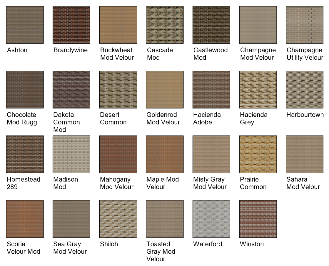
Here is a quick look at the materials in a Revit project (click to enlarge).
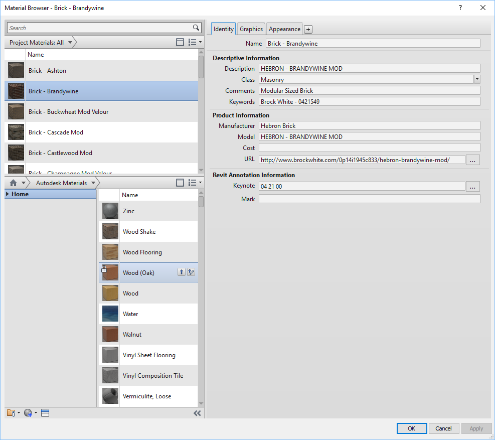
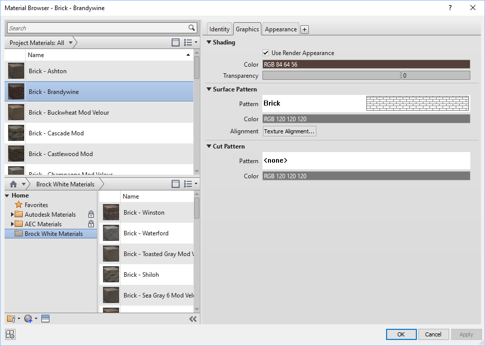
The next three images show the material definition for one of the brick materials.
Identity tab includes information about the product and a URL link for more information on the supplier/manufacturer's website.
The
Graphics tab has the shading color defined by the
Render Appearance and the
Surface Pattern matches the brick size/pattern.
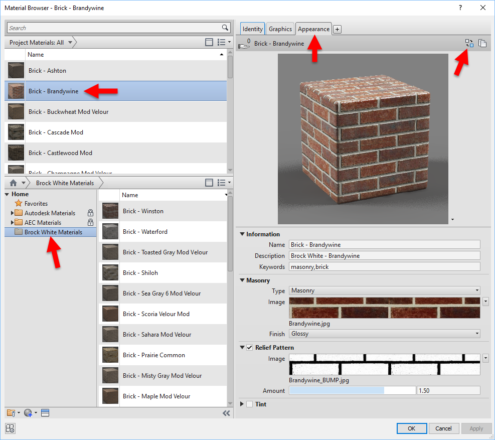
The
Appearance tab defines the realistic/rendering/VR texture. Notice this is a "
Masonry" material asset type and it has two images assigned. In this case, the surface pattern is a Posterized version of the original image file and the joints have been made completely solid. This step creates a little more distinction in the relief. It is perfectly fine to just use the original material as the relief (I do it often).
- FYI: I have noticed, that somethings the advanced materials get washed out in Enscape. In this case, this should be changed to a "Generic" material.
I do not recall why the
Finish is set to
Glossy. Below is a close up view of the material. The white highlights are related to the glossy setting and the current sun position in the view.
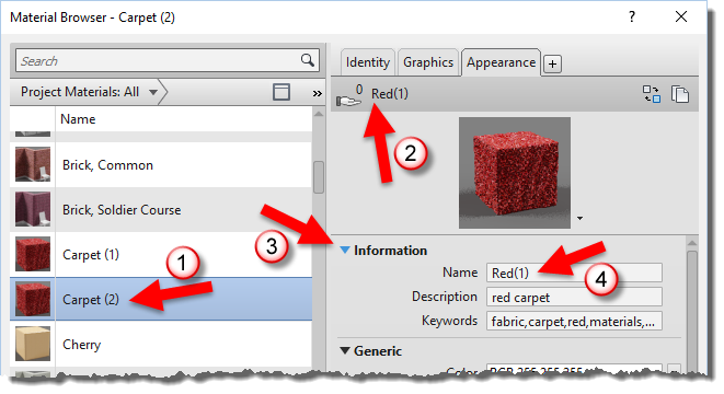
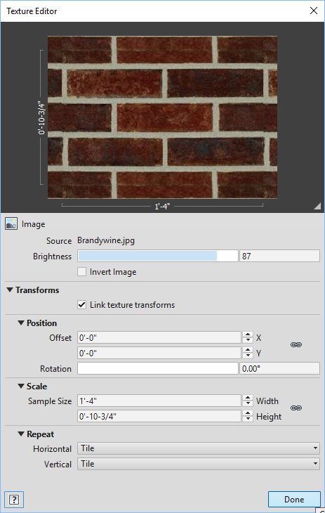
Clicking on the image swatch opens the
Texture Editor. Here is where the size of the texture is defined (i.e.
Scale parameters). This is also where the material is set to
Repeat vertically and horizontally.
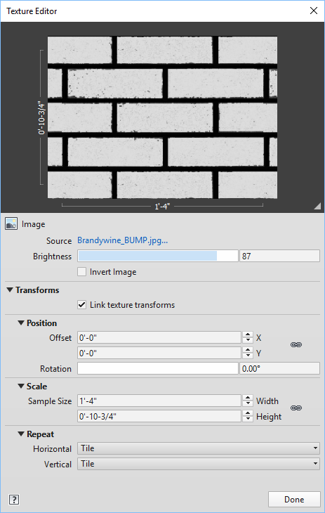
The same values are entered for the
Relief Pattern image.
The
Material Browser has an icon in the lower left which allows you to
create a new material library or
open an existing one. For the brick material library I simply created a new library, which involved providing a name and location for the ADSKLIB file.
I placed all the image files (textures) in a folder along with the ADSKLIB file on the server so everyone has access to it.
Anyone using these materials will need to add this path to the
Additional Render Appearance Paths in Revit's
Options dialog. If this is not done, the material will be gray. These special paths can be incorporated into a deployment. I have several in my deployment; for brick, Herman Miller, Haworth, etc.
Anyone who needs access to this library can use the
Open Existing Library option in the
Material Browser dialog (shown previously). Make sure the
File of type is set to ADSKLIB (not structural property set).
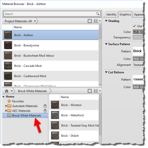
Once loaded, the new library is listed in the
Library Panel as shown below. Materials can be loaded into the current project, just like you do with the Autodesk provided materials. Unless the custom library is in a read-only folder, project materials can be dragged into the custom library as well.
When a material is saved to a custom material library, it includes the main material and its assets (i.e. appearance, thermal, structural). Sometimes, we just want to change a brick material already defined in the project; because it is used by several walls, families, etc. In this case, it is easier to modify the existing material.
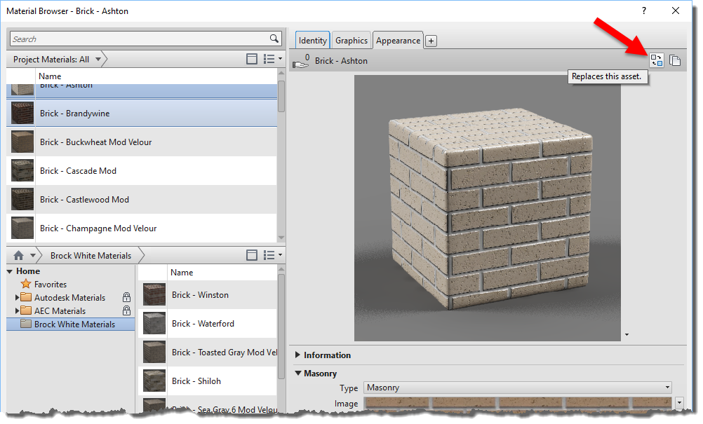
It is possible to replace a material's asset with another one...
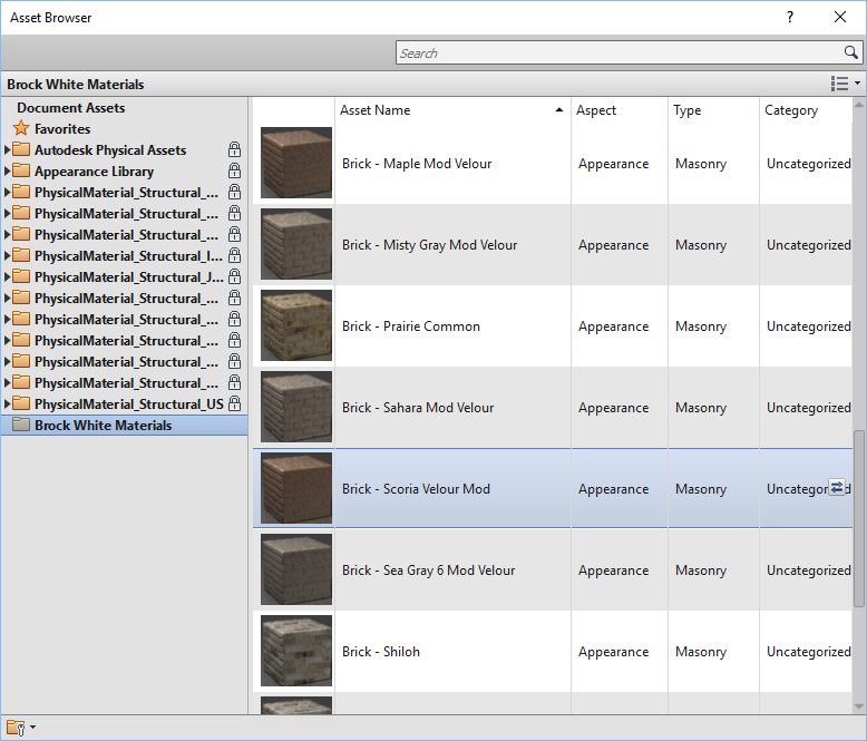
In the
Asset Browser, we can also load the custom material library. This gives us direct access to the appearance assets associated with the main materials as shown below.
If needed, the material assets can be modified apart from the main material. This may not need to be done very often, at least in this example. However, when you need to do it, the process is not very intuitive. From the
Manage tab, select
Additional Settings and then
Materials Assets.
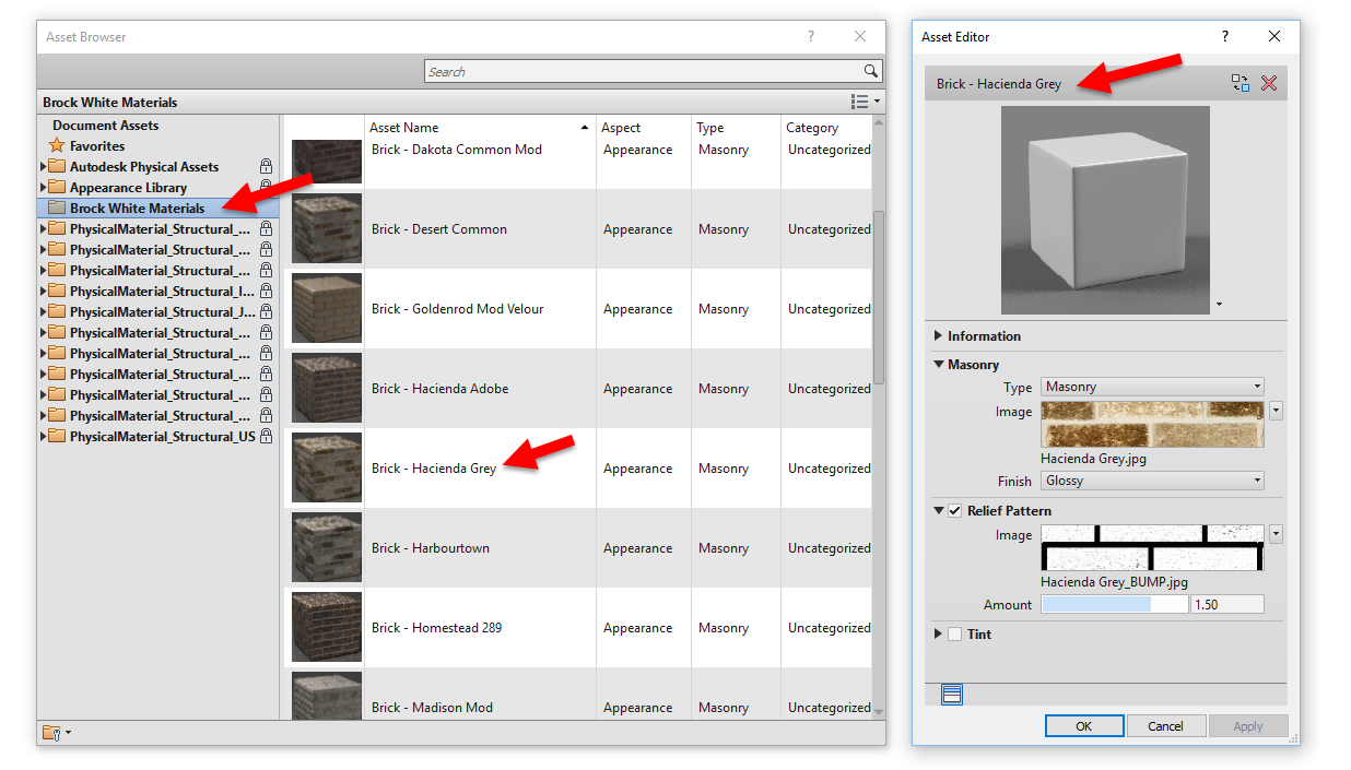
When both the
Asset Editor and the
Material Browser are open, double-click on a material to load its settings into the adjacent
Asset Editor dialog as shown below.
This is a little bit of a tangled web, but getting a handle on this will make the design process and visualization efforts a little more efficient!