
 |
Typical Problem: two walls (vertical) and a ceiling (horizontal)
|
 |
Solution:
Add a sweep to the bottom of the wall
|
The gypsum board profile for the sweep can be parameterized, so you have one for each stud size.
Here is how it’s done…
Creating a Profile for the Sweep
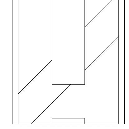
First, create a simple Profile in the family editor. This profile should be set to the thickness of your gypsum board, and the length equal to the depth of your studs.
You can add parameters/dimensions to this profile and then create Types to accommodate various conditions.
 |
Profile: Simple profile create to represent the gypsum
board on the bottom of the wall
|
Setting up the wall type
The next step is to set up a special wall type in your project (or better, template). Duplicate your typical wall type; this is the one you normally use for soffits and bulkheads in Revit now. Add the prefix “Soffit” to all the wall types to sort them in the Type Selector. This wall type could still be based on your standard wall type. For example: M3 Soffit, where M3 is the name of the typical wall type.Now you need to edit the structure for the new soffit wall type. As seen in the Edit Assembly dialog below, you need to set the View option to “Section” to be able to work with Sweeps.
 |
Edit Assembly dialog for soffit wall
|
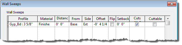 |
Wall Sweeps dialog for soffit wall
|
Wall Function
Now that you have a separate wall type, you should set the type parameter Function to Soffit. |
Soffit wall settings
|
Examples
The following images highlight the results of this effort.The first image shows a bulkhead with two hard ceilings engaging it. The Join command was used to get the materials to clean up. If you want the hard ceiling framing to extend to the bulkhead studs, you need to manually edit the sketch in plan, and make the edge of the ceiling touch the edge of the stud Layer.
- TIP: In this example, the stud layer was unlocked within the wall, so the gypsum board could be shown stopping apart from the wall stud layer.
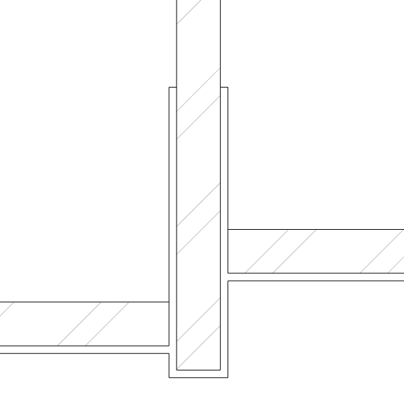 |
Bulkhead with hard ceilings (joined)
|
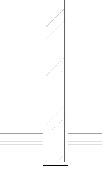 |
Bulkhead with ACT ceilings
|
- FYI: all these ceilings were drawn with the Automatic sketch option.
 |
Soffit condition
|
Not Perfect
So what’s the downside to this process? You get an extra line in the ceiling plan, which represents the back side of the gypsum board on the (soffit) wall. With lineweights and printing, this ends up looking more like a heavy line, rather than two lines (because they are so close together). I know of no way to get around this. You remove it manually, using the Linework tool set to Invisible. But that is a lot of work, and probably not worth the effort.Interior elevations do not have this problem. They look great.
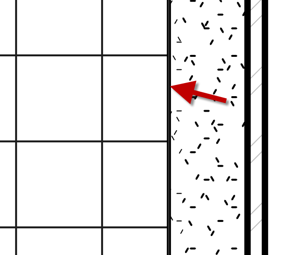 |
Extra line appears at soffit
condition in RCP
|
TIP: Changing the value for Line Weight number 2 will adjust the way fill patterns print in Revit (Manage tab à
Additional Settings à Line Weights). Be careful, however, as you could also change other
lines which have been set to this line weight number as well.
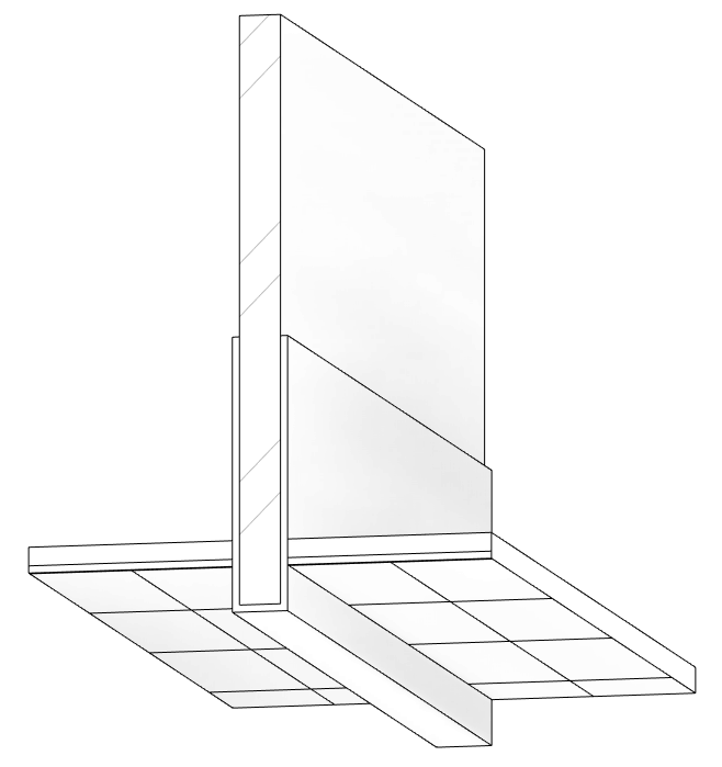 |
3D view with a Section Box
|
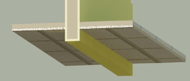 |
Rendered 3D view with a Section Box
|
This workflow is easy to setup in a template and use in a project. Good luck!