
I plan on writing a few short posts to cover just walls in the content of energy modeling. I will start with these three topics:
- Massing
- Revit walls
- Window to Wall Ratio (WWR)
We can perform an energy analysis against simple Revit massing. In the images below I created a super simple mass. This mass extends below level 1 to define a basement area. I selected the mass and used the Mass Floors button on the Ribbon to specify Basement and Level 1 for this specific element.
- FYI: If I did not specify Mass Floors, the entire element would be seen as a shade surface. This is helpful when representing adjacent buildings.
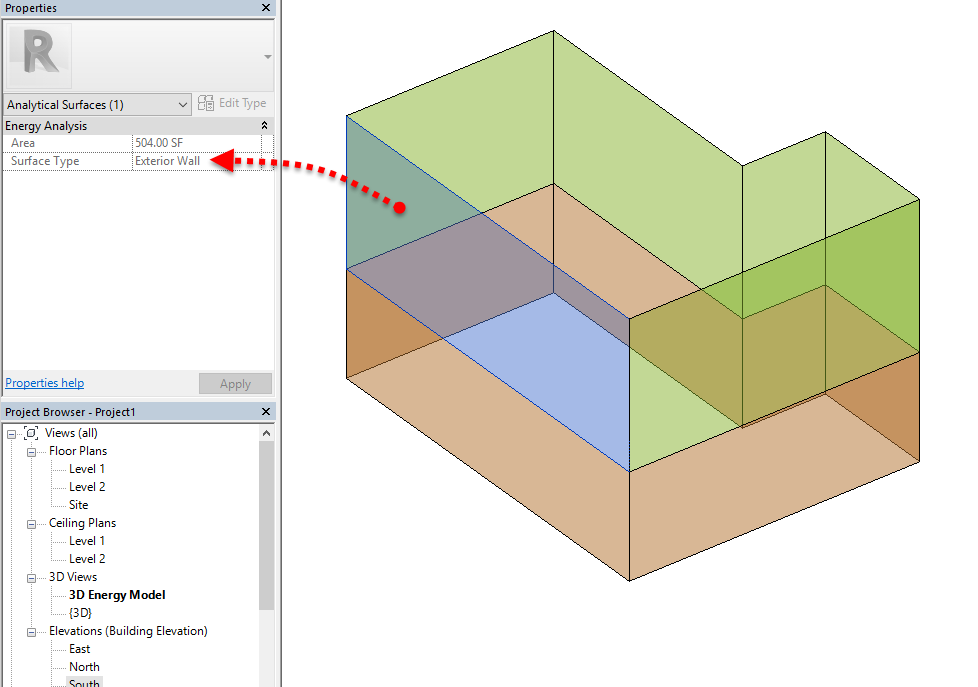 |
| EAM with an exterior wall selected |
 |
| EAM with below grade wall selected |
The image below shows an extreme example of no insulation so it is super clear what is happening when we get into Insight. Notice, this is set in Conceptual Types.
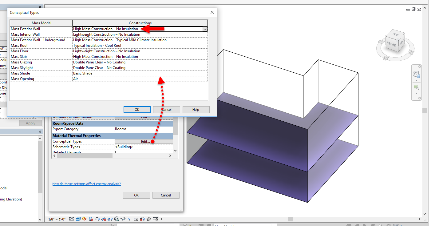 |
| Exterior walls set to uninsulated in Conceptual Types |
- FYI: I used to think the "BIM setting" replaced the input it aligned with on the Cost Range slider, but as you can see below it is just positioned along side it; notice Uninsulated is still a separate option even though it is the same value as the "BIM setting".
 |
| Wall construction result in Insight |
If we apply an override in Schematic Types, this takes precedent over the Conceptual Types setting... but just for the categories selected. In the example below, only walls are overriding the Conceptual Types settings. Here I go towards the other end of the spectrum with an R38 wall construction.
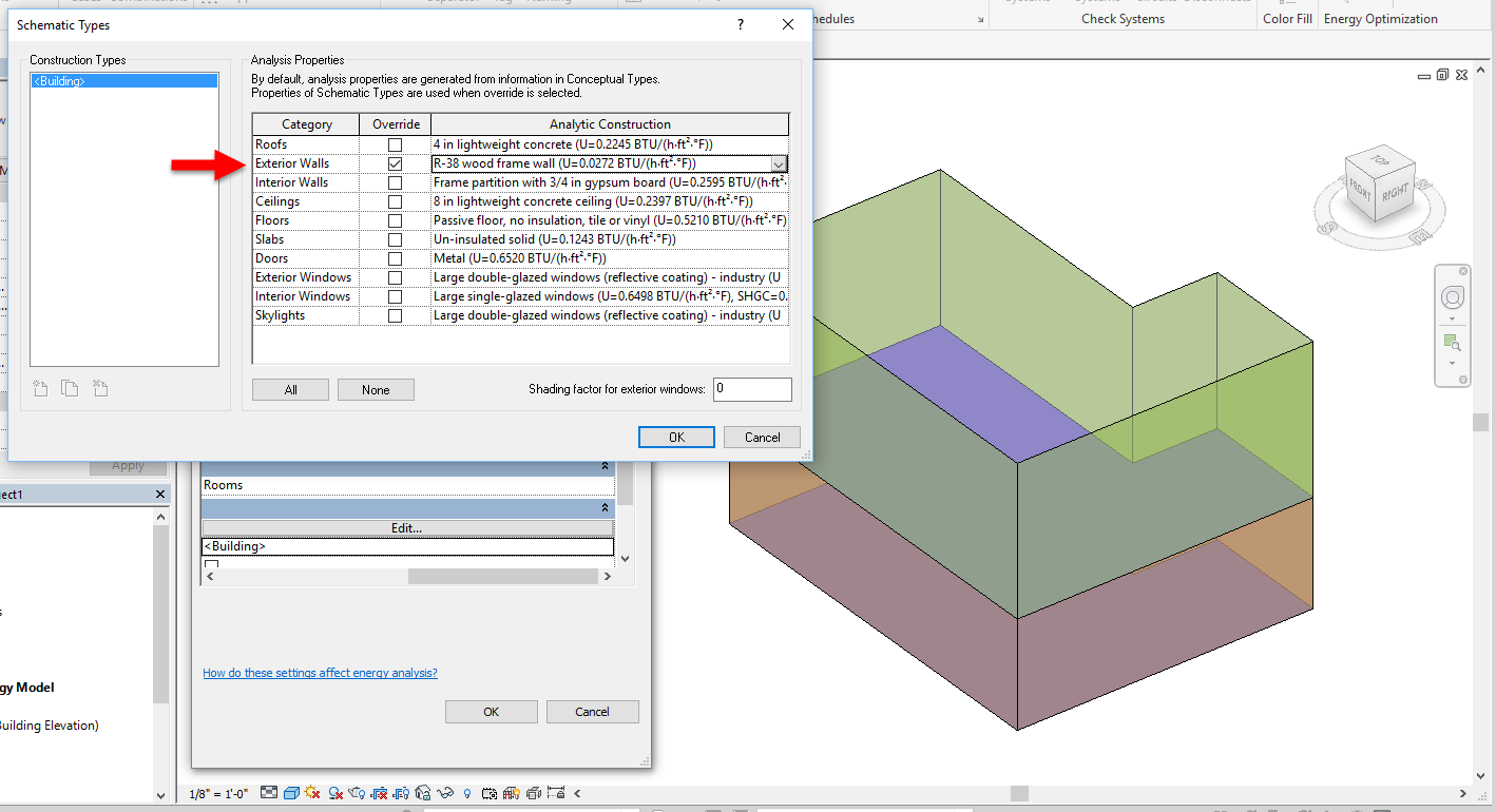 |
| Wall value override selected in Schematic Types |
 |
| Wall construction result in Insight |
The Conceptual Types options are somewhat limited, Schematic Types have a lot more options, and when we get to using Revit materials to define thermal properties there is no limit to the number of options we could have (as we will see in a later post).
I was working with one of our architects this week and she noticed that Schematic Types even has a Straw Bale option as seen in the image below!
 |
| Straw bale wall construction option within Schematic Types |
The great thing about Insight is we can dynamically modify these inputs apart from the Revit model. However, this information is helpful to understand so you can set some baseline inputs, e.g. based on your state's energy code or ASHRAE 90.1, within your template. And, as the project progresses and decisions are made, those decisions can be captured within the BIM.
Stay tuned for more...